An antenna rarely comes off the board at 50 ohm. The usual fix is a small matching network of inductors and capacitors, worked out on a Smith chart from a VNA measurement. Done by hand that means drawing arcs, guessing values, ordering the nearest standard parts and finding out on the bench that the real parts behave differently.
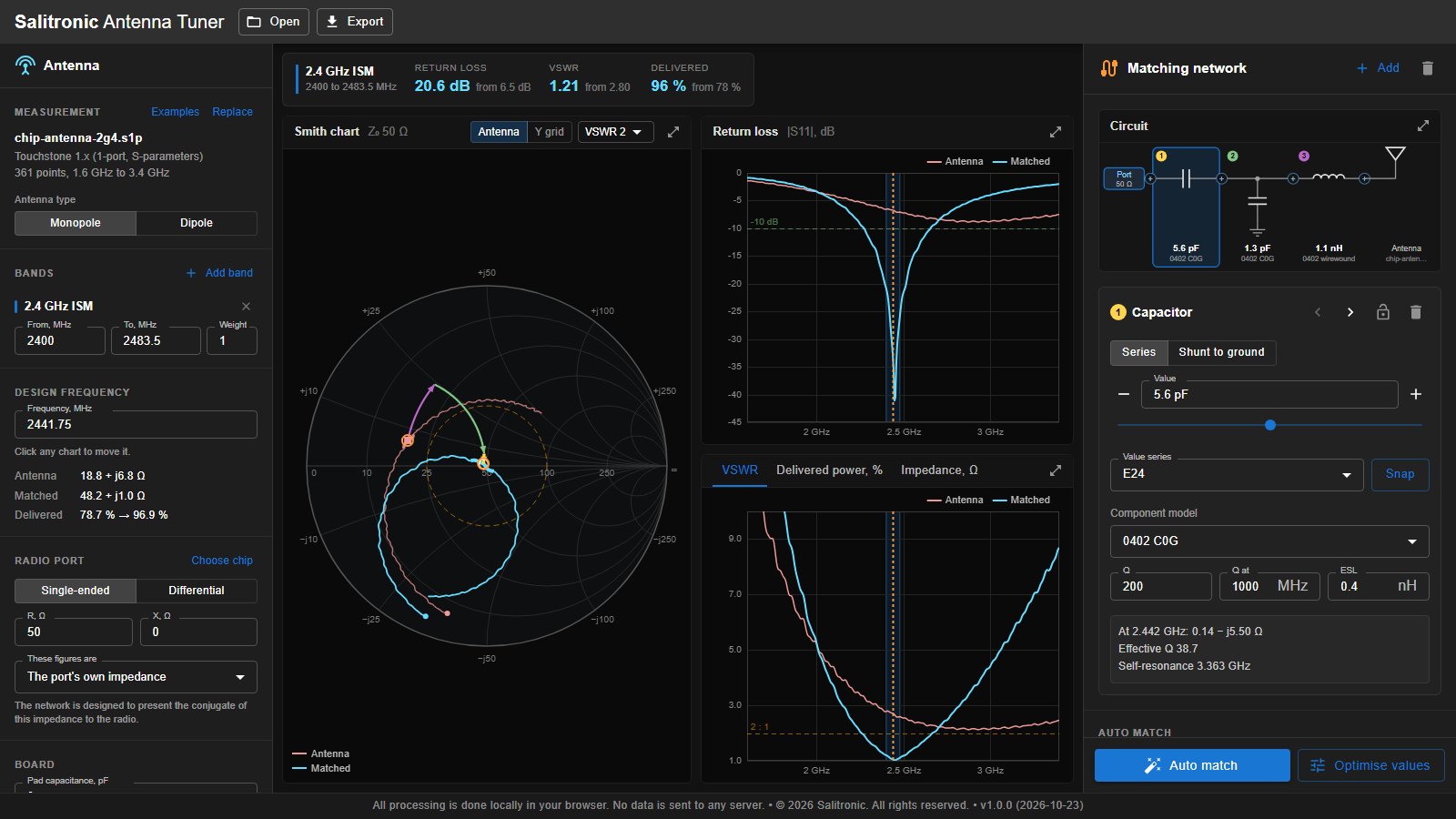
The Salitronic Antenna Tuner loads the measured S11 and shows it on a Smith chart with return loss, VSWR, impedance and delivered power. You build the matching network by hand or let auto match search every ladder topology, using inductor and capacitor models with real Q, self-resonance and solder pad capacitance. Results use buyable E-series values. It runs in your browser, it is free, and your measurements never leave your machine.
What It Does
Reads Your Measurement
Touchstone 1.x and 2.x files with any number of ports (.s1p, .s2p, .sNp, .ts), CITIfile, and CSV or text exports with S11 as real and imaginary, magnitude and angle, dB and angle, or impedance R and X. Column layout and frequency units are detected automatically and can be overridden.
Interactive Smith Chart
The antenna and the matched result on one chart, with zoom and pan, an admittance grid, a VSWR circle and a cursor readout of impedance anywhere on the chart. At the design frequency each matching part draws its own path, so you can see exactly what it does.
Return Loss, VSWR and Power
Return loss, VSWR, impedance and delivered power across the sweep, with your bands shaded. Hover any chart to read every chart at that frequency. Each band gets its worst case return loss, VSWR and delivered power, before and after matching.
Matching Network Builder
Series and shunt inductors, capacitors and resistors, transmission lines, open and shorted stubs, 0 ohm links and unfitted positions. Click a part to edit it, or scroll the mouse wheel over it to step through standard values while the charts update live.
Auto Match
Searches every series and shunt ladder up to eight positions, or a topology you fix yourself (Pi, T, or position by position), across one or more weighted bands. Values are snapped to E12, E24, E48 or E96 and refined at the standard values, so the result is something you can buy.
Real Component Behaviour
Inductors and capacitors carry Q and self-resonance, with typical presets for 0201, 0402 and 0603 wirewound, multilayer and C0G parts. Solder pad capacitance is added at every node. Vendor S-parameter files can be loaded for exact parts, and delivered power counts the loss in the matching parts, not just the mismatch.
Differential Radios and Baluns
Match a differential radio output to a monopole, or a single ended port to a dipole. Parts on the balanced side are fitted as pairs. Use an ideal balun, a vendor 3-port balun file, or let auto match design a discrete LC lattice balun, kept resonant at the band centre so its outputs stay balanced.
Chip and Band Libraries
Published RF port impedances for transceivers from TI, Silicon Labs, ST, Microchip, Nordic, Espressif, Renesas and others, each linked to the manufacturer document. A searchable band library covers cellular 2G to 5G, GNSS, Wi-Fi, Bluetooth, Zigbee, LoRa, Sigfox, UWB, ISM, RFID and more.
Export
The matched response as a Touchstone .s1p file for your simulator, a parts list as CSV with pair quantities for balanced sections, and a project file that saves the measurement, bands, network and settings together.
Who Uses It
- Hardware engineers tuning a chip or PCB antenna after the first prototype comes back from the VNA.
- RF designers checking how much a matching network really costs in loss once part Q and self-resonance are included.
- Engineers moving a design to a new radio chip who need to match its published optimum load impedance.
- Teams without an RF simulation licence who want a proper Smith chart workflow in the browser.
- Educators and students learning impedance matching with real measurements and real parts.
Related Reading
- Antenna Design: choosing and placing a PCB or chip antenna before you tune it.
- RF Minimum Board Size: how small a board can be before the antenna stops working well.
- PCB Impedance Control: getting the feed line to 50 ohm in the first place.
- Inductor and Transformer Design: why real inductors have Q and self-resonance.
- CE and FCC Certification: what a good match means for radiated power and compliance.
- RF Range Calculator: link budget and range for the matched antenna.
- Gerber Analyzer: the companion PCB tool, including antenna simulation from Gerber files.
- RF Design Services: antenna tuning and RF layout done for you.
Frequently Asked Questions
What measurement do I need?
The antenna's complex reflection (S11) across the band, measured at the point where the matching network will connect, usually with the VNA calibrated to the end of a pigtail or test fixture. Magnitude-only data (return loss or VSWR without phase) cannot be matched, because the phase decides which parts are needed.
Which file formats does it accept?
Touchstone 1.x and 2.x (.s1p, .s2p, .sNp, .ts) with S, Y or Z parameters in RI, MA or DB format, CITIfile (.cti), and CSV or text files. For a multi-port file you choose the antenna port, or use the differential impedance of two ports for a dipole measured arm by arm.
How is the matching network modelled?
As a cascade of two-port networks between the radio port and the antenna. Inductors carry series loss from their Q, scaled with frequency, and parallel capacitance that sets their self-resonance. Capacitors carry ESR and series inductance. Lines and stubs are lossy transmission lines, and every soldered node gets the pad capacitance you set. Delivered power is the share of the available power from the radio that reaches the antenna, so it includes both the mismatch and the loss in the parts.
How does auto match choose a network?
It optimises every ladder topology up to the size you allow, or only the topology you specify, against your bands and their weights. Each candidate is searched globally, refined locally, then snapped to the E-series you chose and refined again at the standard values. Results are ranked by worst case performance across the bands, with a small preference for fewer parts. The best result is applied straight away; hover the others to compare them on the charts.
Can it match a differential radio?
Yes. Set the radio port to differential and enter its impedance, or pick the chip from the library. For a single ended antenna the network needs a balun: add an ideal one, load a vendor 3-port balun file, or let auto match design a discrete LC lattice balun along with the matching parts. A dipole can be matched directly from a differential port.
What is the difference between optimum load and port impedance?
Some datasheets give the impedance the chip wants to see (the optimum load), others give the chip's own impedance. The tool asks which one you entered and matches to the right target: exactly the optimum load, or the conjugate of the port impedance. Entries in the chip library are labelled from the source document.
Can I use real component data?
Yes. Load the manufacturer's S-parameter file for a specific inductor or capacitor (most vendors publish series-mounted .s2p files) and place it as a measured part. A 3-port balun file from the balun maker can be used the same way.
Are my files uploaded to a server?
No. Everything runs locally in your browser. Your measurements never leave your machine.
Can an engineer tune my antenna instead?
Yes. The Antenna Tuner is built by Salitronic, and George Saliba, an electronics design engineer with 20+ years of experience, offers RF design services including antenna matching and RF layout review.